Building an Electret Microphone with an LM324N
A tiny electret capsule makes a tiny signal. Bias and coupling make it usable; an optional LM324N preamp raises it for a 3.5 mm line input.
A quick explanation. Then the full story.
Watch the short, then scroll down for the details, diagrams, and context behind it.
Open on YouTube ↗A microphone capsule is not a finished microphone
The electret capsule is the smallest part of this build, but it is also the part that makes the rest of the circuit necessary. Sound moves its diaphragm. The capsule's internal field-effect transistor turns that movement into a changing electrical signal. The signal is small, and the transistor needs a little DC current before it can produce one.
I wanted to see that entire path rather than hide it inside a ready-made microphone module: capsule → bias resistor → coupling capacitor → LM324N preamp → output capacitor → audio jack.
The Short above is Part 1 of my Homemade Alexa project. This article zooms in on the microphone signal path behind that build.
The LM324N is an optional preamp stage, not part of the electret capsule itself. A capsule still needs the right bias current and a compatible audio input. If the destination already has a suitable microphone preamp, you can omit this LM324N stage and follow that input's bias and wiring requirements instead. The complete circuit below includes the preamp because it is designed to feed a stereo line input, which typically needs a larger signal than a bare capsule provides.
This is a 5 V reference circuit, not a record of measured results. The 1 µF input capacitor and the 10 kΩ / 2 kΩ gain pair are the values discussed for this build. Other values below are starting points to verify against the actual capsule, supply, and destination input.
The parts on the bench
| Part | Reference value | Job |
|---|---|---|
| Two-terminal electret capsule | 1 | Converts sound into a small voltage variation |
| LM324N, DIP-14 | 1 for this line-input version | Optional preamp that amplifies the capsule signal |
| Microphone bias resistor | 2.2 kΩ | Supplies current to the capsule's internal transistor |
| Midpoint divider resistors | 10 kΩ × 2 | Make a 2.5 V reference from 5 V |
| Input bias resistor | 10 kΩ | Holds the amplifier input at the midpoint |
| Gain resistors | 10 kΩ feedback, 2 kΩ to VREF | Set the non-inverting voltage gain near 6 |
| Output resistors | 1 kΩ × 2, plus 100 kΩ | Feed two line-input channels and discharge the output capacitor |
| Capacitors | 1 µF, 10 µF, 47 µF, 100 nF | Couple audio and steady the supply/reference |
| 3.5 mm TRS jack or plug | 1 | Connects to a stereo line input |
| Regulated 5 V supply, breadboard, wires | As needed | Power and assembly |
The capsule's two leads are not interchangeable. On many capsules the lead connected to the metal case is ground, but I would confirm the markings or the capsule datasheet rather than guess.
The circuit, one stage at a time
Open the full-size schematic ↗ · Reference values are shown where your component values were not specified.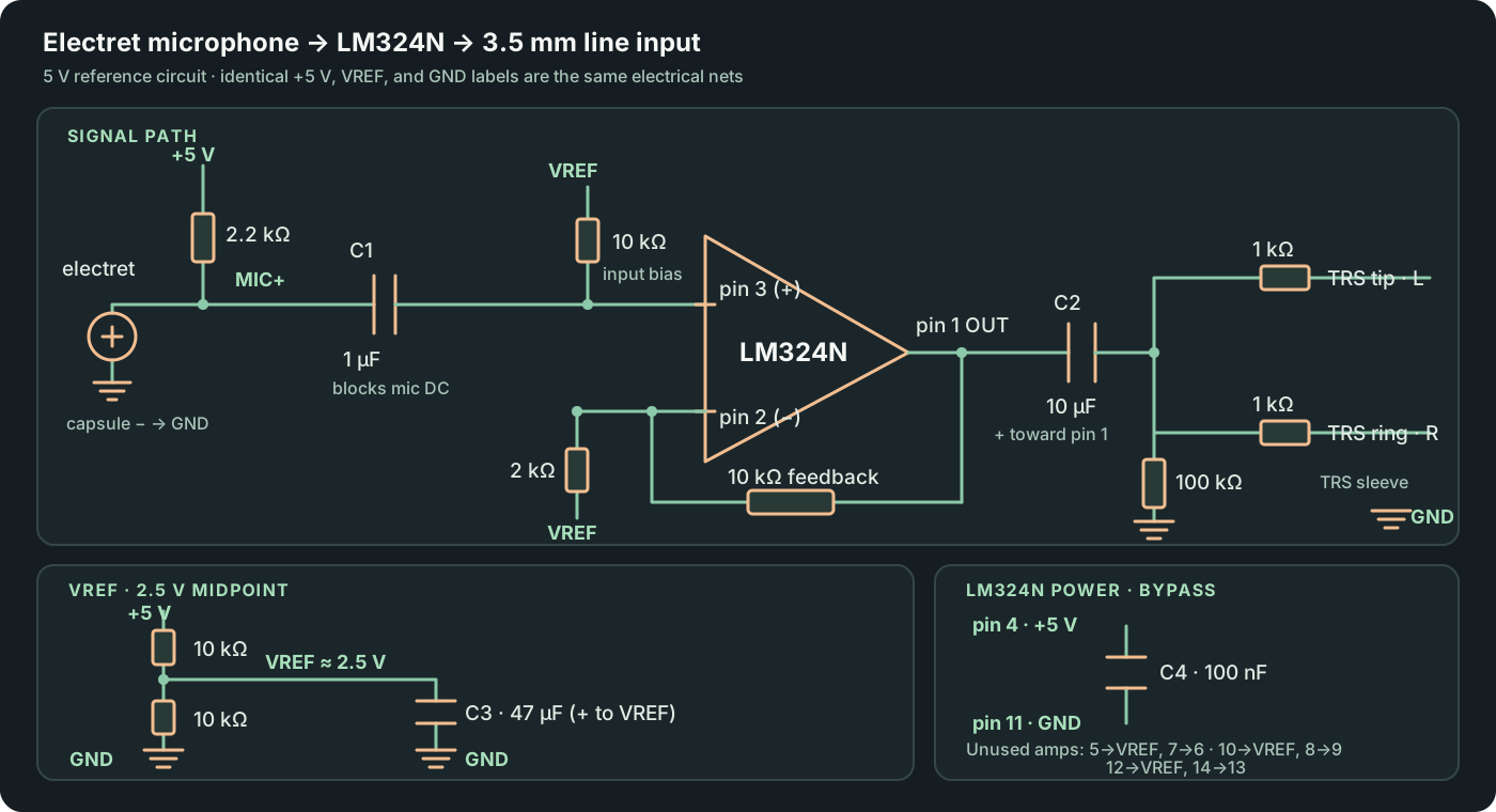
The full schematic shows every connection in the version with the optional LM324N preamp. Open it at full size to trace a wire, then use the numbered panels below when assembling each stage.
Two 10 kΩ resistors divide 5 V into VREF ≈ 2.5 V. The capacitors steady VREF and the chip supply. The 2.2 kΩ resistor supplies the capsule's internal FET. Audio appears as a small change at MIC+. C1 removes the microphone's DC level. The 10 kΩ resistor then holds LM324N pin 3 at VREF. 10 kΩ feeds pin 1 back to pin 2; 2 kΩ connects pin 2 to VREF. This gives about 6× AC gain. C2 keeps the 2.5 V midpoint out of the recorder. Tip and ring receive mono audio through separate resistors. Connect every GND shown here together, including the electret return and TRS sleeve. Place the 100 nF bypass capacitor physically close to LM324N pins 4 and 11.
Read the panels in number order. They show electrical connections, not physical breadboard positions. Check every net against the pin numbers before applying power. A film or bipolar 1 µF capacitor avoids an input polarity decision; if using a polarized capacitor, measure the DC voltage on each side and put its positive lead toward the higher voltage. The 10 µF output electrolytic has its positive lead toward LM324N pin 1, which sits near the midpoint, and its negative lead toward the jack. The 47 µF reference capacitor has its positive lead at VREF.
1. Give the electret its bias current
The 2.2 kΩ resistor connects the capsule's positive lead to 5 V. Its other lead goes to ground. The resistor lets the capsule's internal transistor operate; the voltage at the capsule output then moves slightly with sound. Different capsules specify different operating currents and voltages, so their datasheet gets the final say on this resistor.
Sound changes the diaphragm's capacitance. The internal FET needs bias current; the resulting small audio change appears on the same MIC+ lead as its DC bias.
If I connect MIC+ straight to pin 3, I carry its DC bias into the amplifier as well. The 1 µF capacitor C1 sits in series between MIC+ and pin 3. After it charges, steady DC does not flow through it. A changing microphone voltage still moves charge across the capacitor, so the small audio variation reaches pin 3.
On the amplifier side, the 10 kΩ resistor ties pin 3 to VREF. That resistor gives the signal a new DC center near 2.5 V. In other words, C1 does not erase the sound: it separates the capsule's DC operating voltage from the amplifier's chosen DC operating voltage.
C1 and the 10 kΩ input bias resistor also form a high-pass filter. Ignoring the capsule's output impedance, 1 µF × 10 kΩ gives a corner near 16 Hz: DC is blocked, very slow changes are reduced, and most speech frequencies pass. The real corner changes with the capsule and any other input resistance. The capacitor will not, by itself, remove hiss or mains hum.
2. Give a single-supply op amp somewhere to swing
The LM324N runs from +5 V on pin 4 and GND on pin 11. Two 10 kΩ resistors make VREF ≈ 2.5 V. The 47 µF capacitor steadies VREF; a 100 nF capacitor belongs close to the chip's power pins.
Use amplifier 1 for this circuit: 3 is +, 2 is −, 1 is OUT. Power the package on 4 (+5 V) and 11 (GND).
The 10 kΩ resistor from pin 3 to VREF centers the audio after C1. A ±5 mV signal then moves pin 3 from roughly 2.495 V to 2.505 V. If centered at ground, its negative half would ask the single-supply op amp to go below 0 V.
3. Set a useful first gain
One of the chip's four amplifiers does the work: pin 3 (+) takes audio, pin 2 (−) senses feedback, and pin 1 is the output. Put 10 kΩ from pin 1 to pin 2 and 2 kΩ from pin 2 to VREF.
gain = 1 + 10 kΩ / 2 kΩ ≈ 6
The resistor returns to VREF so the output also rests near 2.5 V. Only the audio variation gets 6× gain: a 5 mV peak at pin 3 ideally becomes 30 mV peak at pin 1.
The LM324N cannot swing fully to the positive rail. Loud input can still clip. If you hear distortion, reduce the feedback resistance, increase the 2 kΩ resistance, or lower the sound level at the capsule.
For the three unused amplifiers, connect each + input to VREF and its output to its − input:
| Amplifier | + input | Connect output to − input |
|---|---|---|
| 2 | pin 5 → VREF | pin 7 → pin 6 |
| 3 | pin 10 → VREF | pin 8 → pin 9 |
| 4 | pin 12 → VREF | pin 14 → pin 13 |
4. Take audio out without exporting the DC midpoint
Pin 1 sits near VREF even in silence. C2 (10 µF) removes that DC before the jack. A 100 kΩ resistor from the jack side of C2 to GND keeps the node from floating.
Separate 1 kΩ resistors send the mono signal to TRS tip and ring. Sleeve connects to GND.
Bring it up without guessing
Before plugging the jack into a recorder, check these points in order:
| Check | Expected reading or action |
|---|---|
| Power off | Pin 4 to +5 V, pin 11 to GND; no supply short |
| Power on | VREF near 2.5 V; pins 3 and 1 near VREF |
| Jack side of C2 | Near 0 V DC, not 2.5 V |
| First recording | Use a line input at low gain; check the waveform before turning it up |
If the recording sounds wrong
- Silence: Check capsule polarity, LM324N pin orientation, sleeve ground, and the input type.
- Hum: Shorten the unshielded mic lead, move the 100 nF bypass close to the chip, and try a quieter supply.
- Harsh peaks: Reduce gain or the sound level at the capsule.
Bias the capsule, give the op amp a midpoint, then remove that midpoint before the jack.
Component references
- Texas Instruments LM324N product page and datasheet — supply range, input/output limits, and pinout.
- Analog Devices electret microphone amplifier lab — electret bias, AC coupling, and single-supply midpoint bias.
- Texas Instruments electret microphone preamp reference design — a tested higher-performance preamp design for comparison.
Field notes
Sign in to leave a comment.
Sign in